
Back in 2009 Alex was experimenting with obsolete neon display technology, ‘nixie’ tubes. One such tube reminded him of old alcohol thermometers, so he decided to build an analogue thermometer around it. This was his prototype: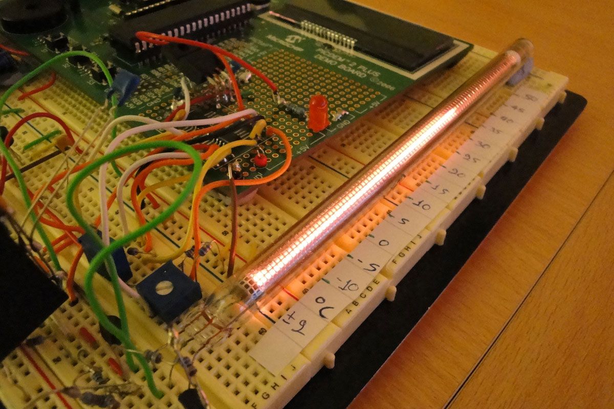
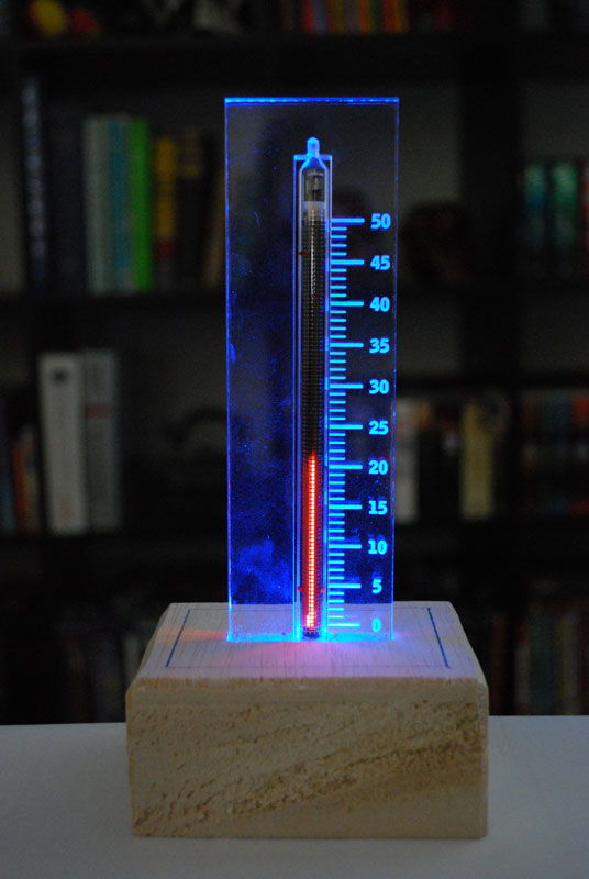
Feeling that his idea was novel, he performed an Internet search only to discover that Simon had assembled the same concept independently. Recognising the weaknesses of the analogue version, he contacted Simon coining the idea of working together on a digital version. This is Simon’s prototype.
Driven by our desire to share their passion for electronics, and not being impeded by the physical distance in excess of 17.000 km, we agreed to collaborate and SALTechips was born.
The product concept revolves around the IN-13 nixie bargraph tube used as the temperature indicator. We wanted to simulate old mercury/alcohol thermometers with a modern twist.
This tube is based on a retro technology that just won’t go away! Before LED and LCD displays, neon indicators were used to display numbers or quantities in all sorts of electronic equipment, from multimeters to truck scales. These tubes (produced in several countries) were slowly phased-out about the same time as the collapse of the Soviet Union. Our stock of IN-13s is date-coded April ’92, one of the last production runs. They are bulky, fragile, expensive and power hungry. But the neon glow has an addictive karma to it, a mesmerising glow hard to describe with words; you just have to see it. Recently this technology is enjoying a revival in clocks, VU meters and thermometers to name a few. You will also find it in power strip indicators and on Wozniak’s hand.
Scale Design
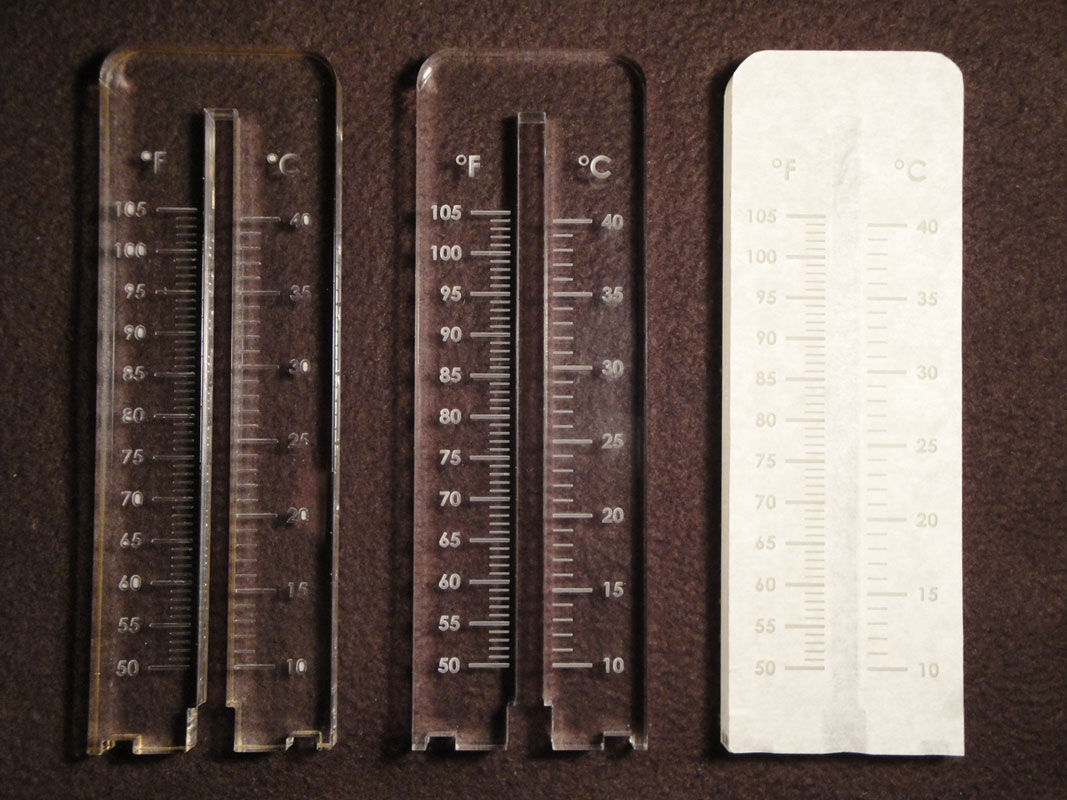
Product design began with the scale. We wanted to protect the glass tube from knocks but not obstruct the view. A thick acrylic piece was LASER cut and a channel machined along its length. The tube slides in the channel and, since it is thinner than the acrylic scale, it is well protected. The numbers and gradations were LASER etched on the acrylic with deep etching to capture more of the light travelling inside the scale. Special care was taken to prevent the sensitive electrodes of the tube from cracking if the scale was stressed. Here are the first prototypes. Clearly the engraving on the first one on the left failed.
Base design
 We also designed the base. Choice of materials and mounting methods was entirely up to us, hence a lot of effort went into finding optimum solutions. We tried several shapes and sizes of bases, even the ‘golden-ratio’ from ancient Greece… At the end we used the one that was just right (see Modelling) and suited the scale dimensions. We decided to use individual pieces of wood to capture the warm glow of the neon tube. As the thermNeon is also available as a kit, we did not want to use glue in the assembly of the base. Finger joints were designed in the base panels that are also LASER cut. To secure everything together a combination of fasteners was selected after many hours of trial and error with standard-length mechanical components. A stain and finish was used to highlight the grain and seal the pores of the wood to provide resistance from the elements and scratches. Here we were trying to figure out a mechanical fastening solution using standard parts:
Modelling
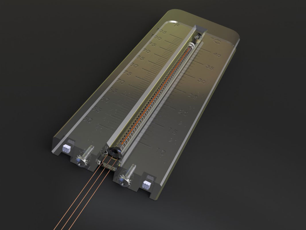
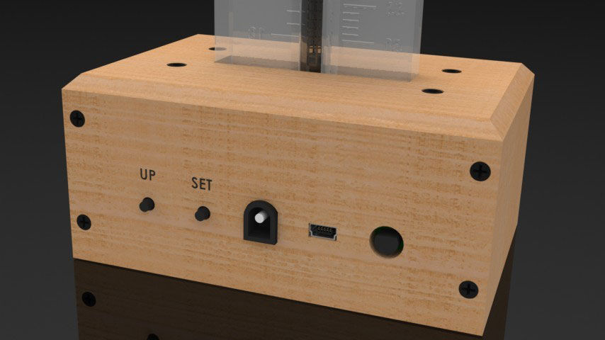
While designing the scale and base we had many different ideas; ‘how would that look, how about this’? It is not economical to make prototypes of all the ideas so we decided to create a full model of the thermNeon (tube, scale, base and PCB). This proved valuable as we could not only check how different wood finishes would look, but also check for clearance problems with the connectors at the back.

Electronics!
 When it came to designing the electronics of the thermNeon we already had a very good idea of what would be involved. We started by interconnecting functional block diagrams of the different subcircuits. The schematic diagrams were then produced in EAGLE and simulated in PSpice, LTSpice and Mindi. Here is our prototype, built to check the results from the simulators. Isn’t the aim with simulators to prove that they work?
Some of the firmware functionality such as the switch-mode controller was implemented in hardware until the firmware was ready; the stuff hanging off board. We decided to use mostly THT components to make assembly more accessible. We are still not sure if most hobbyists are comfortable with full-SMT board?
Firmware
The firmware was written in C in MPLAB X using the C18 compiler. We put everything in 1 C file to make compiling easier. About ¼ of the time went into documenting the C statements to improve readability and serviceability. A PIC MCU was selected as we both had a toolsuite running. The PIC18F1330 contains 3 hardware PWM channels, making it easier to control the number of PWM channels in the thermNeon (6 in total). The remainder of the PWM channels were implemented in software and assigned to lower-priority functionality. The most challenging part of the firmware was the colour mixing for the scale illumination. Two RGB LEDs are assigned a 4-bit intensity value per die for a total of 4096 colours. The RGB values are calculated by a function that accepts an HSV colour representation, calculated depending on the read temperature, hot/cold user temperature setpoints and hot/cold user colour settings. Consequently these two functions have the largest Flash memory footprint. The EEPROM library used to store and recall user settings was copied and modified from a computer server water-cooling project.

Testing
Testing is not to verify that everything works, but to find what doesn’t and correct it. Besides all the standard electrical tests on the thermNeon itself, we tested the power supply bricks from our suppliers as we had not worked with them in the past and wanted to build trust. Due to the large number of units to test, a script was written for a Maynuo M9712B electronic load. We also put the themNeon in an environmental chamber to test its accuracy over the displayed temperature range and also its durability over the commercial product temperature range.
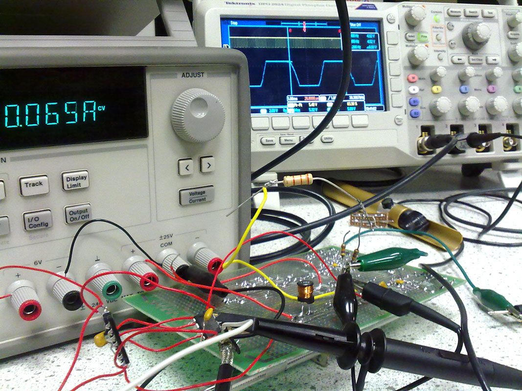
Here is the matrix board prototype on the bench when the gated oscillator power supply controller was being tested.
Manuals
 We strongly believe that a project or product has failed if one needs to refer to the manual to get the core functionality to work. Let’s face it, user manuals are rarely read before plugging the product in. But every now and then you need to setup for some unusual measurement or change a rarely used setting and for that a manual is useful. We wrote a User manual and also included a summary of the settings under the unit’s base for quick reference. A lot of effort went into the Assembly manual for the kit and covering tricky assembly stages. Don’t leave it to the designers to decide what is covered – they know too much. Give a kit to a friend and take notes while they are building it!
Getting it out there
By now we had an expensive prototype that no one knew about. In order to share our product with the world we had to negotiate favourable component costs with multiple suppliers across several countries and continents. We vividly remember rejecting ludicrous offers from a couple of suppliers. Always do your homework before asking for a quote.
The final challenge was to share our excitement about our product with the rest of the world, some call it marketing. We identified our audiences, designed a website and online store, photographed the completed product, made a promotional video, had the product reviewed, approached retail shops…the list is long and ongoing.
To conclude, it has been a long journey from the original idea to the finished product. The electronics is only part of what one needs to consider and put in place before making the product available to others. But seeing someone that you have never met praising the outcome of your work and taking one for home cannot easily be described and is very motivating for the products to come!


