
introduction
A small number of ИН-13 (or IN-13) nixies have demonstrated unstable operation, whereby the glow is unexpectedly interrupted or, in the worst case, extinguished. The intermittent symptoms would normally be attributed to a significant drop of anode voltage (e.g. 40 Volts) or malfunction of the constant current driver. However, the electrical parameters measured at the tube terminals are consistently correct.
To explain this behaviour, a mechanism is proposed that introduces parasitic current leakage paths inside the tube. The mechanism, originating from cathodic sputtering, is present in all glow discharge tubes to a varying extent. Contrary to numerical indicator tubes, the analogue nature of the IN-13 is what makes it highly susceptible to this mechanism.
The mechanism
A ceramic washer is used at the base of the tube to mechanically support the electrode structures. Ceramic is used as it can withstand the high temperature developed from the glow discharge. It is a good insulator under these conditions, effectively electrically isolating the electrodes. The washer contains holes for the electrodes to pass through (see fig. 1). The openings are wider than the electrodes by ~0.3 mm. The remaining gap acts as an insulator, however the electrodes do make intermittent contact with the walls of the holes.
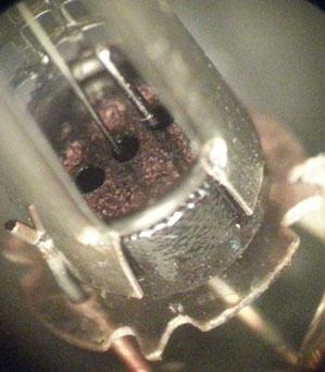
During manufacturing, but also during normal operation, the cathode material (molybdenum) is ejected by cathodic sputtering. The material is deposited on the glass envelop of the tube and all other internal surfaces (see fig. 2). As there is no mica shield to protect the washer from sputtered material (typical in audio pre-amp vacuum tubes), it is also coated with molybdenum. Some material will also be deposited inside the washer’s holes.
parasitic resistances formed by deposition of cathode material.
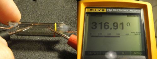
Molybdenum is a good electrical conductor (see fig. 3), having half the conductivity of aluminium. Consequently, the surface of the ceramic washer is no longer an insulator. Due to the intermittent contact of the electrodes to this conductive surface, parasitic current leakage paths are formed. The paths can be modelled by resistances, widely varying over time and sensitive to temperature variations and mechanical vibration.
The same mechanism is present at the top washer, although not as pronounced as
- there is no auxiliary cathode
- the glow discharge spends less time near the top of the tube.
In-circuit effects
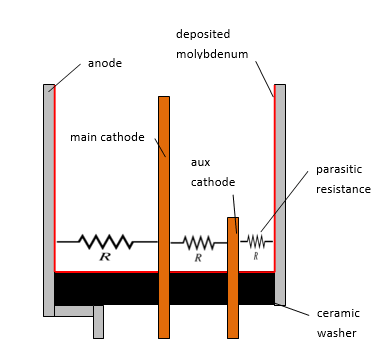
A typical precision constant current sink circuit, commonly used to drive the IN-13 tube is shown in fig. 4 with the parasitic resistors Ra, Rb and Rc added.
Resistor Rc forms a path between the main and auxiliary cathodes of N1. The voltage regulation action of N1 causes both K and K2 nodes to be at approximately the same potential. Therefore very little current will flow through Rc. In the extreme case that Rc is of a very low ohmic value, the auxiliary cathode current would flow through the current sink, introducing an error. It would not however extinguish the glow of any of the two cathodes.
Resistor Rb forms a path between the anode and auxiliary cathode. Due to the low current that flows through the auxiliary cathode, Rb does not need to be of a very low ohmic value to extinguish the auxiliary cathode. If this occurs the main glow will no longer be anchored at the base of the tube.
Similarly to Rb, Ra bypasses the main cathode. Unlike Rb, a much larger current normally flows so the required parasitic resistance to cause significant errors will be lower.
Experimentally, Rc=2MOhm was enough to disturb the auxiliary cathode glow and Rc=400kOhm completely extinguished it. For Ra=5MOhm the change in glowing length of the main cathode was visible, Ra=10kOhm halved the length of the glow and Ra=2kOhm completely extinguished it. The circuit of figure 4 was used for these experiments with 2mA of main cathode current. These results confirm the expected behaviour by the introduction of these parasitic current paths.
Combating the mechanism
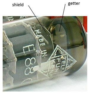
Avoiding the mechanism is not possible given the principle of operation and construction of the tube. Several vacuum tubes of the same era as nixie tubes used a shield between the evaporating getter and top mica washer (see fig. 5). The shield stopped conductive metal from being deposited onto sensitive electrodes. Unfortunately the designers of the IN-13 did not include such a shield.
Minimising the deposited material can reduce the chances of the parasitic paths being formed. This can be achieved by avoiding cleaning of the cathode surface by sputtering whenever possible and operating the tube strictly in its normal glow region (i.e. within specified current limits).
It is theoretically possible to remove the deposited material from the washer by a brief application of high voltage and current between the tube’s terminals. If the energy pulse is shorter than the tube’s formative lag, then the tube will not fire and the deposited material will evaporate. The energy required to evaporate the deposited metal is much higher than the energy required by the tube during normal operation. If the pulse is too long, the tube will fire, damaging itself or exploding. The formative lag is variable, so this method is unpredictable and dangerous.
The most effective way of guarding against this mechanism and the one applied by SALTechips is screening of the tubes prior to use and shipping. Screening is performed by operating the tube while exposing it to vibrations and thermal cycling. The tube is then operated under supervision for one week. If any signs of unstable operation are observed the tube is marked and discarded. Before shipment the tube is tested once again as at the beginning. Rigorous screening of the tubes minimises the chances of parasitic current paths being formed during the lifetime of the tube or product.


