
Fundamentals
The ИН-13 (or IN-13) is part of the family of cold cathode gas discharge tubes. Unlike their big cousins, the thermionic tubes, most types of cold cathode tubes do not utilise a glowing-hot cathode. What is more, cold cathode tubes in general do not operate under a high vacuum but are filled with an inert gas at a pressure much below atmospheric.
To summarise its operation, we can’t think of a more appropriate way than an I-V plot of a simplified cold cathode tube setup (figure 1).
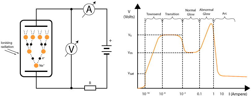
The Townsend avalanche process is indicated inside the cold cathode tube.
In the setup a sealed glass tube is filled with Neon gas. A metallic plate is positioned at each end of the tube and then connected to a power supply. The plate connected to the positive terminal of the power supply is the anode, while that connected to the negative terminal is the cathode. The voltage across the tube is increased while the current is measured and plotted.
The gas will normally behave as an insulator thus preventing any current from flowing. However, in practice cosmic radiation (highly energetic subatomic particles) will intermittently ionise Neon atoms, generating negatively charged electrons (e-) and positively charged Neon ions (Ne+). If a small voltage is applied across the tube, the electrons will be attracted to the anode and the ions to the cathode. Most particles will not reach the plates due to collisions with other particles, or neutralisation from particles with an opposite charge. As the voltage is increased, the percentage of particles reaching the plates increases, leading to an increase in current. Eventually, a saturation point is reached where all particles reach the plates (VSat of figure 1).
As the potential increases further still, the charged particles gain higher and higher speed as they are attracted to the plates. A point is reached where the charged particles have sufficient speed (i.e. kinetic energy) to liberate electrons from other Neon atoms upon collision with them. Electrons are also liberated by Neon ions striking the cathode. This positive feedback multiplication mechanism, termed Townsend avalanche after John S. Townsend, results in an exponential rise of charged particles and therefore a rapid increase of current. The maximum voltage reached in the Townsend region is termed the striking or ignition voltage, Vs.
Once the tube has been ignited, the current flowing must be limited to prevent catastrophic damage to the tube. The current limiting role is performed by a resistor (R in figure 1) connected in series with the power supply. In the transition region any attempt to raise the current through the tube results in the creation of an opposite voltage gradient inside the tube (space charge) and the voltage across the tube falls until a minimum is reached. The tube enters the normal glow region.
In the normal glow region the voltage across the tube is approximately constant. This voltage is termed the maintaining voltage Vm and is lower than the striking voltage. In the normal glow region the number of charge carriers per unit area (current density) is also constant. Consequently, as the current flowing through the tube is increased, the glowing region over the cathode will spread.
With the cathode fully covered by the glowing region, any further increase in current will increase the current density and the tube will enter the abnormal glow region. In this region the potential markedly increases with current. The power dissipated in the tube as heat also rapidly increases.
A point is reached where the cathode is heated to sufficient temperature for thermionic emission of electrons to take place, similarly to a thermionic tube. The additional charge carriers lead to further increase in current and an arc discharge is formed.
The appearance of a cold cathode discharge
The same conceptual setup as in figure 1 is used again, only this time the current through the tube is set to a level immediately before the abnormal glow region. In other words, the tube is operating in the normal glow region with maximum current. The luminous and dark regions of the discharge along the length of the tube can be seen (figure 2), together with the electric potential and the field strength.
Beginning at the left side of the tube in figure 2, the cathode, there is a dark space termed Crookes dark space after William Crookes. It is in this area that most of the voltage drop occurs. The area is dark, as electrons emitted from the cathode from ion bombardment are accelerated by the strong local field. However the electrons don’t immediately have enough energy to ionise Neon atoms.
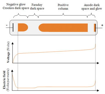
Once electrons have gained sufficient energy, Neon atoms are ionised at the beginning of the area termed negative glow. At gas pressures of 20 Torr the negative glow extends for approximately 1mm. A common misconception is that the negative glow is on the surface of the cathode, possibly due to the fact that the negative glow is the familiar glow that covers the cathode following its geometric shape.
With increasing distance from the cathode the number of collisions decreases and the electric field is low. As a consequence, another dark area is formed, termed the Faraday dark space after Michael Faraday.
Towards the right side of the Faraday dark space the field begins to rise again, although to a much lower level than the Crookes dark space. Ionisation in this area, termed the positive column is likely due to the random velocity of the electrons rather than their drift velocity under the influence of the electric field. If the anode is brought closer to the cathode, the positive column will become shorter. If the anode is brought inside the area of the Faraday dark space then the positive column will not appear. Most gas discharge indicator tubes, including the IN-13, are designed with the anode close to the cathode so that the positive column is not formed.
Internal construction
Construction of the IN-13 tube is simple (see figure 3). The tube is a glass cylinder 160 mm long with a diameter of 9.5 mm. Information on the type and pressure of gas, or gas mixture used to fill the tube is not easily available. Neon is the main component present, although a fractional amount of Argon might be added to the tube to form a Penning mixture. The maintaining potential of the tube is 94-99 Volts, which is lower than values published for pure Neon/Molybdenum tubes at pressures between 13 and 47 Torr (maintaining potential of 111 and 104 Volts respectively). This fact might support the case of a Penning mixture being used in the IN-13 tube.
The tube encloses three electrodes, each individually connected to a pin at the base of the tube. The construction and role of each electrode is described below.
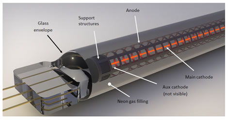
The first electrode is a solid 120mm long Molybdenum rod positioned at the centre of the tube and running over the tube’s length. This electrode serves as the main cathode. Molybdenum is chosen as the cathode material as, in combination with Neon, it gives a low striking voltage (approximately 155 Volts for Molybdenum, compared to 218 Volts for Copper). As described earlier, the glow covering the cathode electrode is proportional to the current flowing through the tube.
The second electrode is the anode, a Nickel cylinder of equal length to the cathode. The cylinder is placed so that the cathode is in its centre and is perforated so that the glow is visible.
The third and final electrode is termed the auxiliary cathode. It is much shorter than the main cathode, approximately 2mm long and also made out of Molybdenum. This electrode is positioned at the bottom of the tube between the anode and cathode. The role of this electrode is to ensure the discharge between the anode and main cathode begins at the start of the cathode and hence the bottom of the tube. A discharge between the auxiliary cathode and anode provides positive and negative ions in its vicinity. The auxiliary cathode discharge thus effectively lowers the breakdown potential locally, forcing the cathode glow to start from the bottom of the tube. In the ИН-9 tube (similar to the IN-13) no auxiliary cathode was used. Instead, a Zirconium spike (even lower striking voltage than Molybdenum) was attached at the bottom of the cathode having the same effect.
The tube contains two more structures in addition to the electrodes. The first structure is the getter and is located at the top of the tube. The getter contains a Barium compound which reacts with remaining air molecules after the tube was first sealed, thus eliminating them. Unwanted gas molecules can also leak into the tube from the connection terminal seals (Dumet seals) at the bottom, but also from hot surfaces like the cathode outgassing.
The second structure is used to support and space all the tube’s internal parts. Sheets of a ceramic material from the mica family of minerals are used for this purpose due to their insulating properties at elevated temperatures.
One of the final steps of production is the cleaning of the Molybdenum cathode from surface impurities introduced during handling. A process termed cathodic sputtering is used, whereby the tube is driven into its abnormal glow region when a large current flows through the tube. The high current discharge causes high energy ions to bombard the cathode, ejecting some cathode material together with any impurities. The ejected material is deposited on nearby surfaces (including non-illuminated regions of the cathode) and on the glass walls. Impurities are thus captured on a thin film away from the cathode. As a side effect, the thin layer of material deposited on the glass also suppresses outgassing from the glass tube.
Limitations
Several phenomena limit the uses and working life of the IN-13 tube. Firstly, cathodic sputtering takes place continuously while the tube is operating, even at a slow rate. Eventually, so much material is deposited on the glass walls that the light output decreases substantially. Depending on operating conditions, this can take several thousand hours of operation to become noticeable.
A second phenomenon is poisoning of the main cathode which is the cause of the familiar irregular ‘jump’ of the glow from one part of the cathode to the next if the IN-13 tube is used in static display applications. There are two mechanisms that cathode poisoning can be attributed to. The first mechanism is contaminants from the gas being collected by sputtered material and deposited on the main cathode. The second mechanism is gases released by the main cathode’s glowing area reacting with the neighbouring, non-illuminated cathode area. Both mechanisms lead to the formation of a contaminated layer on the cathode which locally changes the tube’s operating characteristics. Fortunately, the cathode surface can be restored by brief cathodic sputtering, similar to the sputtering performed as part of the normal manufacturing process.
Finally, the tube cannot instantaneously respond to external signals. Considering the case of igniting the tube, earlier we saw that external ionising radiation is needed for the glow discharge to begin, even if voltage is applied to the electrodes. The delay until the ionisation process takes place is random. The delay is termed statistical lag and is defined as the time until an electron is produced by ionising radiation. The statistical lag is of the order of seconds if the tube is not primed with materials that do not naturally produce ionising radiation. A related type of delay is the formative lag, defined as the time taken for the current to increase from the initial saturation value to the equilibrium value in the region of normal glow. The formative lag is of the order of microseconds.
On the other hand we consider the case of extinguishing the tube. After removal of power, a finite time is taken for the gas to become de-ionised and the tube characteristics restored. In particular, the insulating properties of the gas must be restored to a point where reapplication of voltage to the terminals does not cause re-ignition. This delay is termed de-ionisation time and is of the order of milliseconds.
These limitations prevent the use of the tube is certain applications such as static displays, prolonged use, or high speed applications (e.g. ON/OFF indicator, tank level indicators and audio peak level meters respectively).
The IN-13 has been out of production for over 20 years. It preceded the era of LED and LCD displays, growing next to the thermionic tube. It is now a piece of electronic display technology history dating back to 1955. The IN-13 cold-cathode gas-discharge tube shares the high voltage requirements and mesmerising neon glow of its numerical cousins, the strictly called ‘nixie’ tubes.
References and further reading
The number of publications is only exceeded by the number of applications of this technology. Here we list some excellent sources relevant to this article.
- Dance, J. B. (1967). Cold Cathode Tubes. London: Ilifee Books Ltd.
- Francis, G. (1956). The Glow Discharge at Low Pressure, in: Handbuch der Physik, ed. by S. Flügge. Berlin: Springer
- Penning, F. M. (1957). Electrical Discharges in Gases. Eindhoven: Philips Tech. Library.
- Weston, G. F. (1968). Cold Cathode Glow Discharge Tubes. London: Ilifee Books Ltd.
- Weston, G. F., & Schagen, P. (1965). Patent No. GB1012229. United Kingdom.


